Overview of SIL and the steps to verification
Introduction
In a chemical processing facility located near a populated industrial zone, a team of engineers is finalizing the design of a pressure protection system for a distillation column. The risks are well understood: loss of pressure control could lead to vessel rupture, fire, or toxic release. The potential impact extends far beyond the equipment—workers, neighbors, and the environment could all be affected.
To prevent this, the team has taken one of the most crucial steps in the safety lifecycle: Safety Integrity Level (SIL) Verification. This process is where engineering design meets risk reduction—where the numbers behind protective systems are tested and verified. SIL Verification is the rigorous, quantifiable step that ensures a safety function will deliver the level of protection it promises.
Understanding SIL and the IEC 61508 Standard
At the core of this effort lies the IEC 61508 standard, the international benchmark for functional safety in electrical, electronic, and programmable electronic systems. It outlines the complete safety lifecycle: from hazard identification to system decommissioning. The goal is clear—to ensure that Safety Instrumented Systems (SIS) perform reliably in response to dangerous conditions.
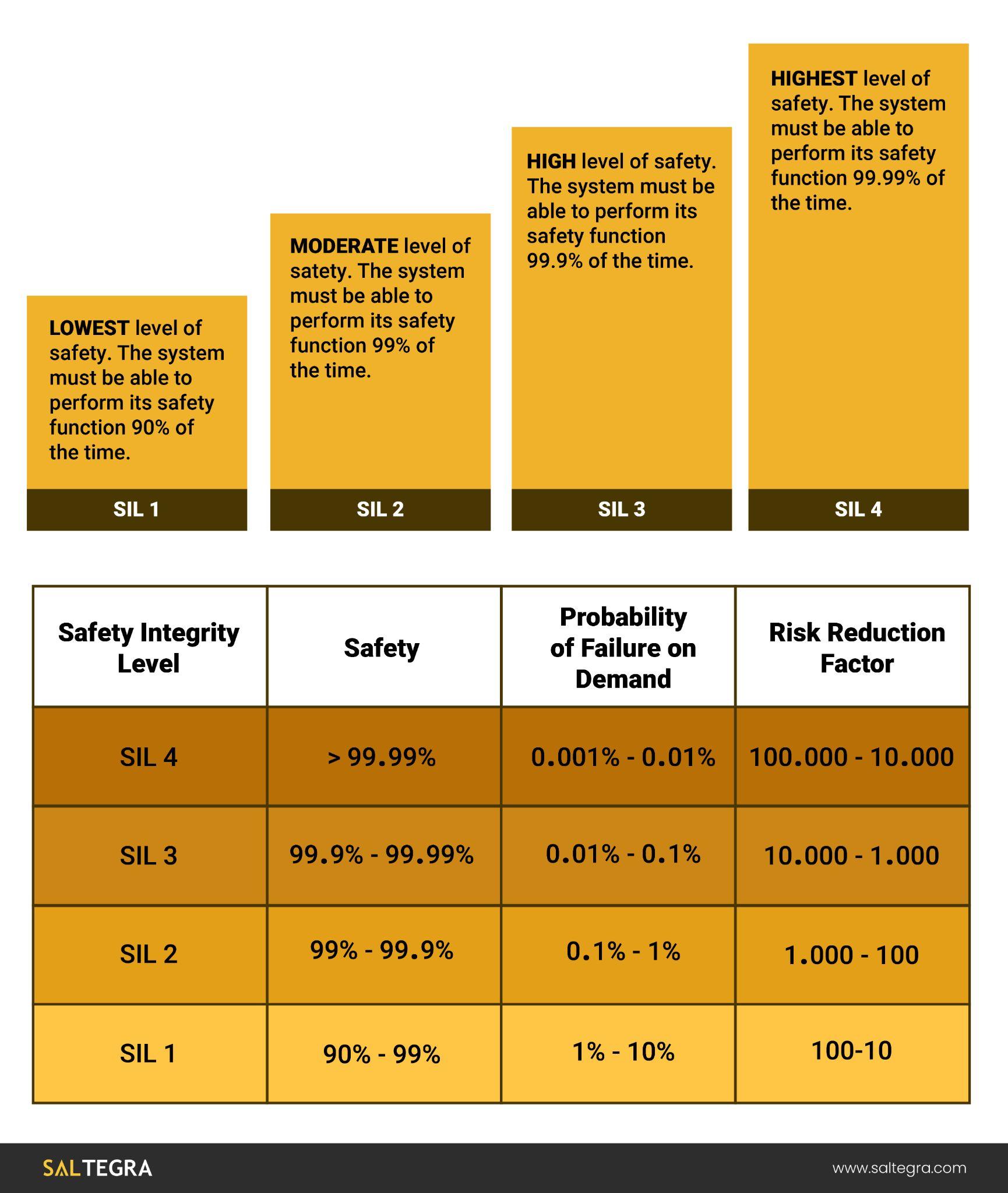
This standard introduces the concept of Safety Integrity Levels (SILs)—quantified categories of risk reduction. SIL 1 represents the lowest level of risk reduction, while SIL 4 is the most stringent. Each level corresponds to a range of probabilities that a system will fail to act correctly when called upon. For example, SIL 2 covers a Probability of Failure on Demand (PFD) between 0.01 and 0.001.
 From Risk to Requirement: The Role of LOPA
In the chemical facility, the engineering team conducted a Layer of Protection Analysis (LOPA) to determine the appropriate level of risk reduction. The LOPA evaluated potential hazards—such as a blocked outlet or control valve failure—and identified existing layers of protection, including alarms and operator intervention. When these weren’t sufficient, a Safety Instrumented Function (SIF)—a dedicated safety control—was deemed necessary.
The LOPA revealed that the existing layers only reduced the frequency of a catastrophic overpressure scenario to once every 100 years. However, to meet the facility’s tolerable risk target of once every 1,000 years, an additional risk reduction factor (RRF) of 10 was required. That corresponds to SIL 2, a level that ensures a PFD no greater than 0.01.
 Performing SIL Verification: Step-by-Step
With a SIL 2 target established, the proposed SIF required verification to ensure compliance. The SIF included a pressure transmitter (sensor), a logic solver (PLC), and a solenoid-actuated relief valve (final control element).
Using a simplified formula for low-demand operations:
PFDavg = (λDU × TI)/2
Where:
- λDU is the dangerous undetected failure rate (in failures per hour)
- TI is the test interval (in hours)
Suppose the failure rates are:
- Pressure transmitter: 100 FITs (1 FIT = 10⁻⁹ failures/hour), TI = 1 year = 8760 hours
- Logic solver: 50 FITs, TI = 8760 hours
- Solenoid valve: 200 FITs, TI = 8760 hours
Converting these:
- Transmitter: λDU = 1×10⁻⁷
- Logic solver: λDU = 5×10⁻⁸
- Valve: λDU = 2×10⁻⁷
Plugging in:
- Transmitter PFD = (1×10⁻⁷ × 8760)/2 = 0.000438
- Logic solver PFD = (5×10⁻⁸ × 8760)/2 = 0.000219
- Valve PFD = (2×10⁻⁷ × 8760)/2 = 0.000876
Summing these gives the total SIF PFD:
PFDtotal = 0.000438 + 0.000219 + 0.000876 = 0.001533
This result confirms the SIF achieves a risk reduction factor of roughly 652 (1 / 0.001533), well within SIL 2 requirements. The verification step demonstrates that the selected components and architecture meet the performance criteria.